
Blog
Keep up to date with what the author has been up to, commentary on current Engineering themes and events below:
●
●
Website Launch! https://readle.co.uk is LIVE!
02/04/2021
Two and a half years ago I set myself a new year’s resolution to create an “Engineering Website” to share useful information, best practice and tools with engineering colleagues throughout the UK. This now feels a very long time ago indeed, but I am very pleased to say that https://readle.co.uk - Readle Engineering Tools - is now LIVE!
It has been a very long road to get to this point, with over 700 files and drawings created (not including revisions and changes) totalling over 1GB of data. I have had to learn numerous programming languages including HTML, JavaScript, CSS and PHP, as well as numerous software and frameworks. There have been many ups and downs during the process, from the agonising hunt for missing semi-colons causing a script to grind to a halt, to the satisfying Eureka moment when the code and website behave as planned.
I would like to thank everyone who has helped along the way, from listening to my monologues or rants about the website (delete as applicable!) to giving advice on content and frameworks. I would particularly like to thank anyone who has kindly given their time to check the website; their help has been invaluable.
Finally, I hope this website is of use to you! If there is any content you would particularly like to see or if you spot any errors, please use the “Contact” section to get in touch! If this website is of use to you, please support the site by sharing with friends, family, colleagues and social media. Thank you!
I hope you enjoy this website!
●
●
Resilience: What is it? Why is it so important? And how can we become more resilient?
November 4th 2019, by Ellie Rozan
Note from the Editor: This is the first in hopefully a series of guest blog posts from other contributors. Guest posts bring a variety of experience and points of view on a new range of topics. Mental health is slowly starting to be more recognised and understood in both Engineering and in wider society and there is now a greater focus being put on mental health in the often macho field of construction. Therefore, I am very glad that the first guest blog post is on the subject of mental health. The Editor is grateful to Ellie for sharing her understanding on www.readle.co.uk.
Resilience: the capacity to recover quickly from difficulties; toughness.
Everyone has experienced difficulties; it is a part of life and without them, you wouldn’t be the person you are today. “What doesn’t kill you makes you stronger, right?” But what if, this wasn’t necessarily the case and in order to become “stronger”, we all need some form of resilience.
To be resilient can have many benefits. It can improve learning and academic achievement, it can lower the number of sick days you have from work, it can reduce risk-taking behaviours like excessive drinking or drugs and ultimately it can improve your physical health and lower the rate of mortality. Pretty great, huh? What might surprise you is there are also different types of resilience. These include:
- Emotional Resilience: How we manage the emotional impact of stresses, difficulties and trauma in our lives.
- Inherent Resilience: The natural resilience which we are born with; which protects us as we grow and helps us to explore the world and learn.
- Adapted Resilience: This is the type of resilience we develop and learn throughout life as we deal with new challenges. It is learnt on the spot to help us manage stress and pain.
- Learnt Resilience: Built over time, we draw on this type of resilience to get through stressful times. It is a resilience in which we develop mechanisms of managing and drawing on strength we didn’t know we had in times when we need it most.
So how do we become more resilient? Some of the most obvious ways to become more resilient are to look after yourself. This includes both your mental and physical health; doing things you enjoy to relax and/or are good at, exercising and eating well. In terms of your mental health, being kinder to yourself is, although sometimes easier said than done, also important.
It is with this point in mind (pun not intended), that I’d like to share an interesting method of building resilience with you. Have you heard of distorted thinking? Maybe you’ve experienced it or maybe you haven’t? Whatever may be the case, one thought to take from it is that this is having thoughts that are not true.
Here are the 7 types of distorted thinking:
- Mind Reading (“My boss doesn’t like me…”)
- Catastrophising (“Nothing will ever be right again”)
- Globalising (“All Mondays are awful”)
- Fortune Telling (“This is going to be the worst day ever”)
- All or Nothing (“I’ve had that chocolate, so my diet’s out the window, I might as well have that wine as well”)
- Strict Demands (“I can’t have any chocolate this week”)
- Labelling (“I’m an introvert so I couldn’t possibly do that”)
These are all types of negative and limiting ways of thinking that can overlap and often have a detrimental effect on how we think about ourselves and connect with others. By being more aware of these distorted and often intrusive thoughts and recognising them as “Fortune Telling” or “Catastrophising”, we can help break the cycle and over time, build our resilience.
What do I mean by the cycle? Well, I’m referring to CBT; Cognitive Behavioural Therapy. It is our (distorted) thoughts, that can (negatively) influence our feelings and our behaviours, which can spiral to negatively impact our mental and physical health.

Interaction between Thoughts, Physical Sensations and our Behaviours
One way of breaking this cycle is to recognise these thoughts; taking a step back and asking ourselves “What’s going on here?” The best way to do this is also to look at the positive and negative in a situation, in other words, balanced thinking. By doing so, you are accepting what may not have gone well but also recognising what did, which can ultimately help to give you a more balanced and realistic view of the situation. It is this balanced way of thinking that can in fact reduce feelings of panic, anxiety and/or depression and over time, ultimately build your resilience, which will only make you “stronger” to cope with the next challenge life throws at you.
●
●
Florida Bridge Collapse – Findings Announced
October 26th 2019, by Doug Readle
On March 15th 2018 a new pedestrian bridge being built for the Florida International University collapsed, killing 1 construction worker on the structure and 5 people on the highway below, 8 other people were also injured in the incident. The US National Transportation Safety Board (NTSB) have now released their findings of what caused the collapse and what lessons should be learned.
The background to the scheme, the design of the structure and the events that led up to the collapse are summarised in a video published on the NTSB’s YouTube channel, repeated below (warning: video shows footage of bridge collapse with workers on the structure):
NTSB video on the background and events leading up to bridge collapse. (Embedded from NTSB YouTube channel)
Although the video states the direct cause of the collapse it doesn’t provide information on what the root causes of the accident were. The final NTSB report that details this has not been published as yet, however an abstract has been published and is available at the following link: NTSB Abstract. The abstract details a number of different findings and include recommendations for different parties to try to ensure a similar collapse does no occur again. The abstract summarises the probable cause of the collapse as follows:
“Probable Cause
The National Transportation Safety Board (NTSB) determines that the probable cause of the Florida International University (FIU) pedestrian bridge collapse was the load and capacity calculation errors made by FIGG Bridge Engineers, Inc., (FIGG) in its design of the main span truss member 11/12 nodal region and connection to the bridge deck. Contributing to the collapse was the inadequate peer review performed by Louis Berger, which failed to detect the calculation errors in the bridge design. Further contributing to the collapse was the failure of the FIGG engineer of record to identify the significance of the structural cracking observed in this node before the collapse and to obtain an independent peer review of the remedial plan to address the cracking. Contributing to the severity of the collapse outcome was the failure of MCM; FIGG; Bolton, Perez and Associates Consulting Engineers; FIU; and the Florida Department of Transportation to cease bridge work when the structure cracking reached unacceptable levels and to take appropriate action to close SW 8th Street as necessary to protect public safety. “
Unfortunately neither the abstract nor the summary video detail the structural reasons for the failure, merely stating that a shear failure occured at the intersection of Diagonal 11 and the deck. Fortunately, in addition to the NTSB’s own investigation the US Department of Labo(u)r have published their own report into the collapse, this is more detailed than the NTSB abstract, this can be found at the following link: OSHA Report This 115 page report goes in to much more detail about the cause of the collapse from both a project point of view and a structural point of view.
The route cause of the bridge collapse was a punching shear failure at the interface of Diagonal 11, the Deck, Column 12 and Diaphragm II. For a structure of this form the end diagonal is usually in compression, while the deck is in tension. At the end of Diagonal 11 where the diagonal meets the deck the axial load in the diagonal is at an angle to the horizontal deck joint, resulting in load being applied to the deck both horizontally and vertically. The horizontal component gives rise to a shear force, between the deck and the diagonal. With the FIU bridge design this load had to be transmitted across a construction joint, where the concrete on one side of the joint had already cured, this gives rise to a line of weakness as the bond between the concrete is poorer.
The OSHA report found that the bridge designers had over estimated the capacity of the shear connection and underestimated the applied load. The underestimation of capacity arose from a misunderstanding of how the compression of a joint effects the shear capacity. In a concrete structure a shear failure can only occur if one side of a failure line can displace past the other. Concrete is a rough material due to the course aggregate present, any failure has to be able to displace the shearing body up and over the aggregate, which is not easy, or break through the aggregate, which is also not easy. If the joint is being compressed while sheared then the amount of “aggregate interlock” is greater, i.e. it’s harder to move up and over the course aggregate, this improves the shear capacity. If the joint was in tension then the opposite is true, the material is being pulled apart, so less “aggregate interlock” is reduced. The OSHA report found that the designers had overestimated the amount of axial compression across the joint, leading to a higher estimate of shear resistance that was there in reality. In addition, the designers had not specified that the construction joint should “intentionally roughened to 1/4″ amplitude”, which would have increased the amount of aggregate interlock across a construction joint.
Once the structure was in place over the carriageway and the post-tensioning bars in Diagonal 11 were released cracks started to occur around Diagonal 11, the Deck and Diaphragm II. Retrospective OSHA calculations estimated that joint was 22% over utilised at this time, I.e. the applied loading was 22% higher than the calculated capacity. This over-utilisation was evident on site by the large structural cracks that were growing by the day.
To remedy the situation the design Engineer instructed that Diagonal 11 be re-tensioned. This additional compressive load in the diagonal increased the aggregate interlock across the construction joint, however it also increased the shear applied across the section at a greater rate. This re-tensioning led to the joint being over-utilised by 45%, making the situation much worse rather than better. During the re-tensioning of Diagonal 11 the structure failed, the interface between Diagonal 11 and the Deck, which had already partially failed, failed completely and transferred load from the diagonal to deck region into the diaphragm, which then failed in punching shear and led to the total collapse of the structure.
The key structural elements are detailed in the photos below, along with sections of the Deck and Diaphragm II showing the region of shear and punching shear failure. It was noted in the OSHA report that a number of vertical and horizontal drainage pipes passed through the area of punching shear failure (as shown below), these would have acted to weaken this region further.
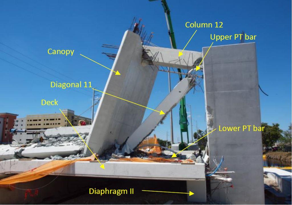
Area at north end of structure post-collapse with key elements labelled. (Image taken from public domain OSHA report and reproduced for educational purposes under conditions of Fair Use)
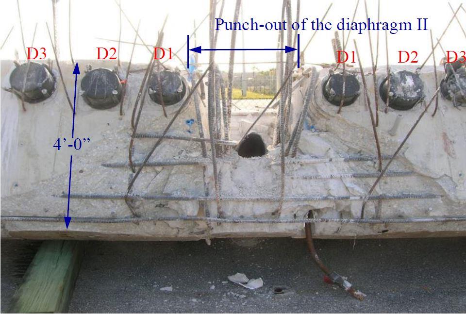
End on view of Diaphragm II showing area of punching shear failure at intersection with Diagonal 11. (Image taken from public domain OSHA report and reproduced for educational purposes under conditions of Fair Use)
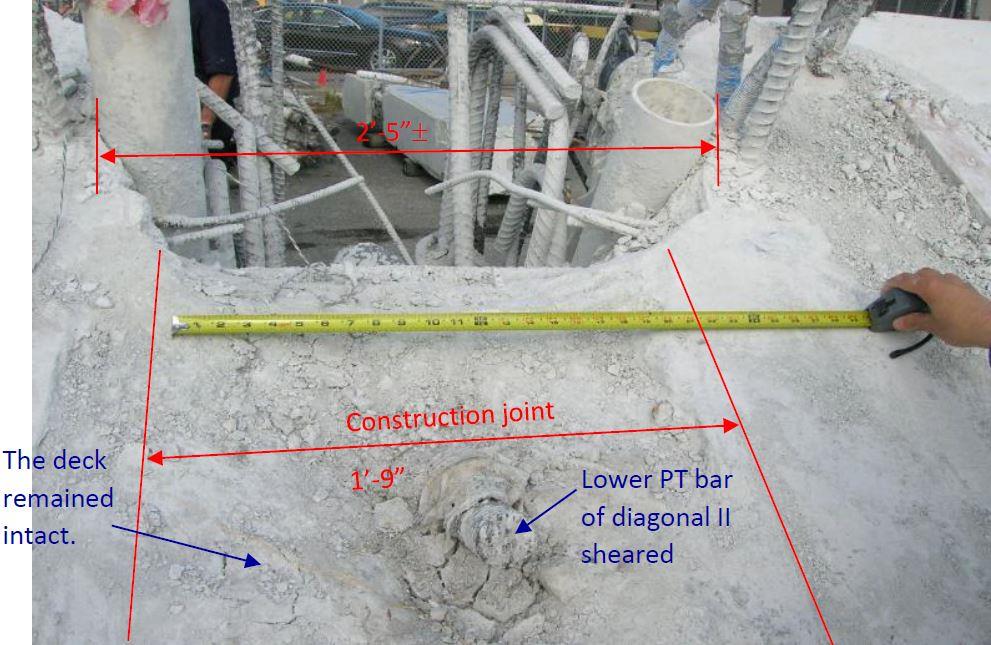
Close up plan view of deck showing the construction joint with Diagonal 11 and area of Diaphragm II that has been punched out. (Image taken from public domain OSHA report and reproduced for educational purposes under conditions of Fair Use)
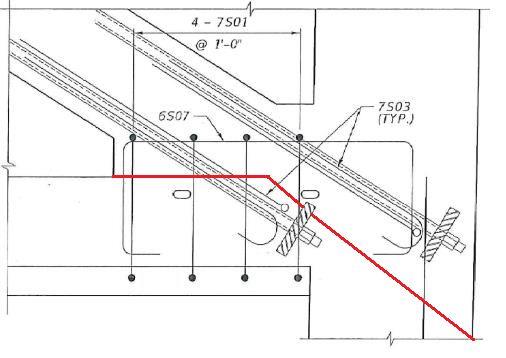
Extract of reinforcement drawing showing area of intersection between the Deck (left), Diagonal 11 (top left), Column 12 (top right) and Diaphragm II (bottom right). Red line added by Author shows the approximate line of punching shear failure. (Background image taken from public domain OSHA report and reproduced for educational purposes under conditions of Fair Use. Red failure line added by Author)
Both the NTSB extract and OSHA report detail a number of project and engineering failures that led to the collapse of the structure, a few key points are summarised below:
- Lack of understanding of the behaviour of a complex structure and whether it had redundancy.
- The design team did not understand the correct loads to use when calculating aggregate interlock and overestimated the shear capacity of the node. They also failed to specify the surface should be roughened on site, to match the calculation assumptions.
- The independent reviewer only checked the capacity of the main elements, not the capacities of the nodes or the individual construction stages.
- The independent reviewer stated that inadequate funds were provided for a full check.
- The seriousness of the cracking was not recognised by the designers, with the design engineers stating numerous times that the cracks were not a concern.
- Lack of ownership and responsibility taken by other member of the project team, including contractor, client and the independant Construction Engineer and Inspector.
- The carriageway below the structure was not closed during the re-tensioning of the Diagonal 11, this would have prevent the deaths that occurred to road users below the bridge.
One aspect of this project that stuck out immediately for me, but that was not really mentioned by either the NTSB or OSHA, but that I feel should have been highlighted was the unusual and arguably unnecessarily complicate outline design. It was decided that the structure should be made to look like a cable stayed structure, but not be a cable stayed structure, this led to the need for fake piers, fake steel tubes and the odd truss deck arrangement, with diagonals of varying angles. Secondly, if an irregular truss structure is required, why choose concrete, a material that is great in compression but needs significant reinforcement or post/pre-tensioning in tension? Adopting a more standard cable stayed steel structure would have been more conventional and would have removed a number of the challenges of this scheme. For me the adoption of a needlessly odd structural form, with ill-suited materials should also have been considered as a root-cause. I sadly suspect the only reason this structural form, that led to unnecessary risk and contributed to loss of life, was adopted purely for reasons of aesthetics.
●
●
Exploring the BFI archives
October 16th 2019, by Doug Readle
I have recently been looking through the British Film Institute (BFI) online archive and found quite a few historically interesting videos. If you are based in the UK you can search the BFI archives and stream the videos online at the following location: https://player.bfi.org.uk/
It’s also possible to explore the archives by filming location, allowing you to find historic footage of areas near you, by using the map search link: https://player.bfi.org.uk/britain-on-film
I have particularly enjoyed watching one of the archive promotional videos from the Dorman Long steel company formally of Teesside.
Video shared with kind permission from the British Film Institute
Dorman Long was a historically important steelworks, producing the steel for a number of famous structures such as the Tyne Bridge, Sydney Harbour Bridge and Lambeth Bridge. Dorman Long was formed in 1875 and in 1877 published its first catalogue of steel and wrought iron sections. Dorman Long continued to produced steel sections and issue useful handbooks until the 1960s. In 1967 the firm merged with other steel producers to become British Steel. Much of Teesside’s steel industry has now closed down.
The legacy company, Dorman Long Technologies, still allows users to download the historic steelwork manuals from the link here. Very useful when undertaking structural assessment of historic structures and also an interesting piece of history.
The video above is a great summary of the steel making process and shows the heavy industry involved in producing construction materials, as well as the energy and raw materials required. Although some of the processes have probably been refined in the intervening 60 years the core process in steel production remains the same.
●
●
Welcome to the readle.co.uk Engineering Tools Blog!
October 6th 2019, by Doug Readle
Welcome to the Readle.co.uk Blog!
I will try to keep the blog up to date and use it to discuss topical subjects within the world of Engineering or just what I have been up to (with pictures of interesting Engineering I have seen!).
I have thought a bit about what to discuss in my first ever blog post, should I make it an in depth critique of the state of Engineering in the UK? Maybe an opinion pieces on some of the key themes or issues in Engineering at present? In the end I settled for sticking to what I know best and have therefore decided to discuss a large historic rail bridge near where I live: Bennerley Viaduct!
Bennerley Viaduct was built in 1887 by the Great Northern Railway to cross the Erewash valley, Erewash River and Midlands Railway. Beyond either end of the Viaduct the Great Northern Railway also crossed the Nottingham Canal to the north east and the Erewash Canal to the south west. The viaduct was built as part of the Great Northern Railway Derbyshire and Staffordshire extension, connecting the coalfields of the Erewash valley with Derby, Nottingham and stations further afield.
The ground conditions around the Viaduct were poor due to the large amount of mining activity in the area, therefore a wrought iron viaduct was chosen over the more conventional masonry arch viaduct. This helped to reduce the total weight of the structure and reduce the risk of settlement. The superstructure is formed of multiple simply supported spans, this allows the structure to deflect to accommodate differential settlement without imposing significant additional loads on the structure, another advantage over a comparable continuous span or a masonry arch viaducts.
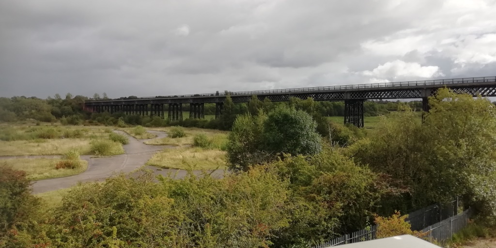
Bennerley Viaduct taken from North West, looking South East. Photo taken from pedestrian footbridge spanning Ilkeston to Chesterfield rail line. (Author’s photo)
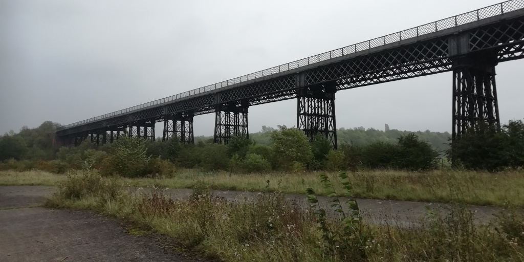
Closer shot showing trestle piers and lattice girder main beams, even the parapets are lattices! (Author’s photo)
Bennerley Viaduct is one of only two surviving Wrought Iron viaducts of it’s type in the country, the other being the Meldon Viaduct in Devon. The original Tay Bridge which famously collapsed in 1879 was of a similar form of construction to Bennerley Viaduct, though Bennerley Viaduct was clearly of a more robust design.
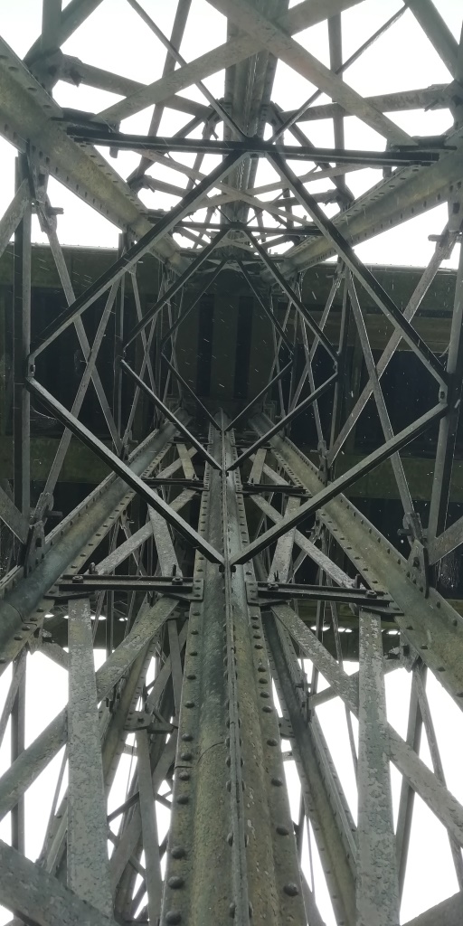
The viaduct is formed of sixteen 76′ 7″ (23.3m) spans, with the total length of the viaduct and approaches being 1452′ (443m) long. Spans are formed of three parallel riveted wrought iron lattice girders, which in turn supports a transverse trough deck. A lattice girder is similar to a truss, however the diagonal elements that form the girder web intersect with each other, often multiple times, whereas a more standard truss will often just have diagonals that only intersect the top and bottom chord. The intersection with other elements helps to reduce the buckling length of the compression diagonals, allowing the web elements to be made of more slender sections.
The substructure is formed of wrought iron trestle piers, comprising 12 fabricated circular hollow column sections arranged in a varying pattern from edge to edge as follows: 1 inclined column, 2 verticals, 3 verticals, 3 verticals, 2 verticals and 1 inclined. This arrangement positions half the columns (3 + 3) almost below the middle lattice girder, as the middle lattice girder supports approximately twice the load of the edge girders this is a sensible arrangement.
The fabricated circular columns are made of four quarter circle flanged sections (quadrants) that are then riveted together. Due to the length of the columns, quadrant sections could not be formed long enough and so shorter quadrant lengths needed to be spliced together. Usually when splicing shorter elements together additional plates are added across the joint to transfer load out of the end of one section and into the start of the new section, these are called splice plates. The circular columns do not have splice plates and instead the joints are staggered, with a joint in one quadrant at one location while the remaining quadrant continue passed the joint, these other quadrants are then jointed further along the column length. This is not the most efficient use of material as areas exist where only a proportion of the full circular section is effect due to the presence of the non-spliced joint.
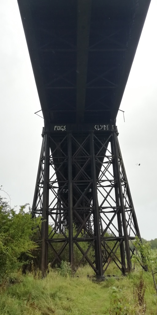
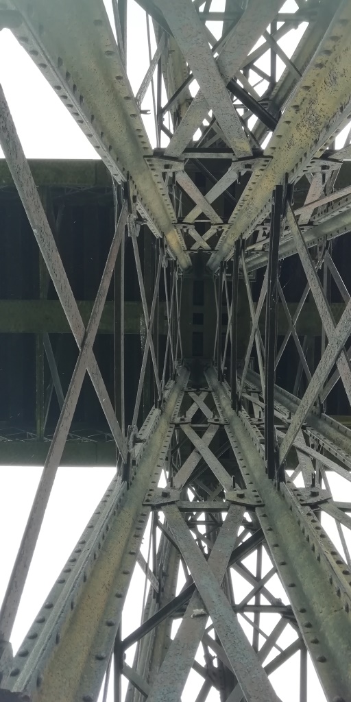
Left: Underside of deck and pier construction. Centre: Edge of trestle pier, riveted tubular columns with bolted bracing. Plan layout of columns roughly square on plan. Right: Inner trestle pier, two additional tubular columns in the centre of the pier creating a layout of two smaller rectangular on plan. (Author’s photos)
The photos above show that most of the trestle diagonals and horizontals are either bolted or wedged together, instead of being riveted like the column sections. This could suggest that the column sections were fabricated either off-site or in a dedicated area nearby, whereas the diagonal and horizontal elements were bolted together in-situ, once the columns were in place. This would prevent the need for riveting at height.
Bennerley Viaduct has been a remarkable survivor over its more than 130 year life. It survived heavy freight traffic for almost a hundred years and then managed to avoid being scrapped following the Beeching Cuts in the 1960s. Bennerley Viaduct also survived an air-ship raid during World War 1, the viaduct and nearby ironworks were one of the targets of the “Great Midlands Raid” undertaken on 31st January 1916. Fortunately the structure wasn’t hit and damage to the nearby area was limited.
The railway line crossing Bennerley Viaduct was closed in 1968 and the viaduct has laid derelict since then. However, a local charity the Friends of Bennerley Viaduct (https://www.bennerleyviaduct.org.uk/) have recently successfully applied for planning permission to reopen the structure as a cycle route. I wish them the very best with their restoration work and I am looking forward to dusting off the bike and cycling across this iconic structure in the near future!
●
●