
Florida Bridge Collapse – Findings Announced
October 26th 2019, by Doug Readle
On March 15th 2018 a new pedestrian bridge being built for the Florida International University collapsed, killing 1 construction worker on the structure and 5 people on the highway below, 8 other people were also injured in the incident. The US National Transportation Safety Board (NTSB) have now released their findings of what caused the collapse and what lessons should be learned.
The background to the scheme, the design of the structure and the events that led up to the collapse are summarised in a video published on the NTSB’s YouTube channel, repeated below (warning: video shows footage of bridge collapse with workers on the structure):
NTSB video on the background and events leading up to bridge collapse. (Embedded from NTSB YouTube channel)
Although the video states the direct cause of the collapse it doesn’t provide information on what the root causes of the accident were. The final NTSB report that details this has not been published as yet, however an abstract has been published and is available at the following link: NTSB Abstract. The abstract details a number of different findings and include recommendations for different parties to try to ensure a similar collapse does no occur again. The abstract summarises the probable cause of the collapse as follows:
“Probable Cause
The National Transportation Safety Board (NTSB) determines that the probable cause of the Florida International University (FIU) pedestrian bridge collapse was the load and capacity calculation errors made by FIGG Bridge Engineers, Inc., (FIGG) in its design of the main span truss member 11/12 nodal region and connection to the bridge deck. Contributing to the collapse was the inadequate peer review performed by Louis Berger, which failed to detect the calculation errors in the bridge design. Further contributing to the collapse was the failure of the FIGG engineer of record to identify the significance of the structural cracking observed in this node before the collapse and to obtain an independent peer review of the remedial plan to address the cracking. Contributing to the severity of the collapse outcome was the failure of MCM; FIGG; Bolton, Perez and Associates Consulting Engineers; FIU; and the Florida Department of Transportation to cease bridge work when the structure cracking reached unacceptable levels and to take appropriate action to close SW 8th Street as necessary to protect public safety. “
Unfortunately neither the abstract nor the summary video detail the structural reasons for the failure, merely stating that a shear failure occured at the intersection of Diagonal 11 and the deck. Fortunately, in addition to the NTSB’s own investigation the US Department of Labo(u)r have published their own report into the collapse, this is more detailed than the NTSB abstract, this can be found at the following link: OSHA Report This 115 page report goes in to much more detail about the cause of the collapse from both a project point of view and a structural point of view.
The route cause of the bridge collapse was a punching shear failure at the interface of Diagonal 11, the Deck, Column 12 and Diaphragm II. For a structure of this form the end diagonal is usually in compression, while the deck is in tension. At the end of Diagonal 11 where the diagonal meets the deck the axial load in the diagonal is at an angle to the horizontal deck joint, resulting in load being applied to the deck both horizontally and vertically. The horizontal component gives rise to a shear force, between the deck and the diagonal. With the FIU bridge design this load had to be transmitted across a construction joint, where the concrete on one side of the joint had already cured, this gives rise to a line of weakness as the bond between the concrete is poorer.
The OSHA report found that the bridge designers had over estimated the capacity of the shear connection and underestimated the applied load. The underestimation of capacity arose from a misunderstanding of how the compression of a joint effects the shear capacity. In a concrete structure a shear failure can only occur if one side of a failure line can displace past the other. Concrete is a rough material due to the course aggregate present, any failure has to be able to displace the shearing body up and over the aggregate, which is not easy, or break through the aggregate, which is also not easy. If the joint is being compressed while sheared then the amount of “aggregate interlock” is greater, i.e. it’s harder to move up and over the course aggregate, this improves the shear capacity. If the joint was in tension then the opposite is true, the material is being pulled apart, so less “aggregate interlock” is reduced. The OSHA report found that the designers had overestimated the amount of axial compression across the joint, leading to a higher estimate of shear resistance that was there in reality. In addition, the designers had not specified that the construction joint should “intentionally roughened to 1/4″ amplitude”, which would have increased the amount of aggregate interlock across a construction joint.
Once the structure was in place over the carriageway and the post-tensioning bars in Diagonal 11 were released cracks started to occur around Diagonal 11, the Deck and Diaphragm II. Retrospective OSHA calculations estimated that joint was 22% over utilised at this time, I.e. the applied loading was 22% higher than the calculated capacity. This over-utilisation was evident on site by the large structural cracks that were growing by the day.
To remedy the situation the design Engineer instructed that Diagonal 11 be re-tensioned. This additional compressive load in the diagonal increased the aggregate interlock across the construction joint, however it also increased the shear applied across the section at a greater rate. This re-tensioning led to the joint being over-utilised by 45%, making the situation much worse rather than better. During the re-tensioning of Diagonal 11 the structure failed, the interface between Diagonal 11 and the Deck, which had already partially failed, failed completely and transferred load from the diagonal to deck region into the diaphragm, which then failed in punching shear and led to the total collapse of the structure.
The key structural elements are detailed in the photos below, along with sections of the Deck and Diaphragm II showing the region of shear and punching shear failure. It was noted in the OSHA report that a number of vertical and horizontal drainage pipes passed through the area of punching shear failure (as shown below), these would have acted to weaken this region further.
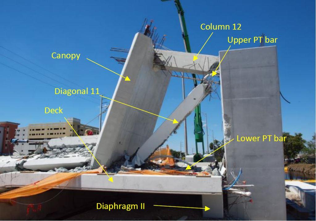
Area at north end of structure post-collapse with key elements labelled. (Image taken from public domain OSHA report and reproduced for educational purposes under conditions of Fair Use)
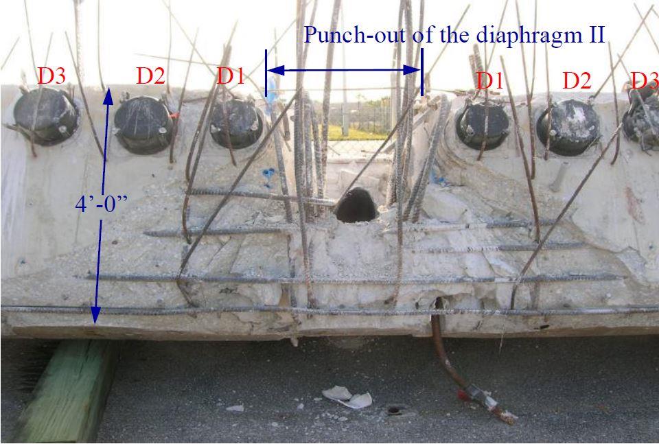
End on view of Diaphragm II showing area of punching shear failure at intersection with Diagonal 11. (Image taken from public domain OSHA report and reproduced for educational purposes under conditions of Fair Use)
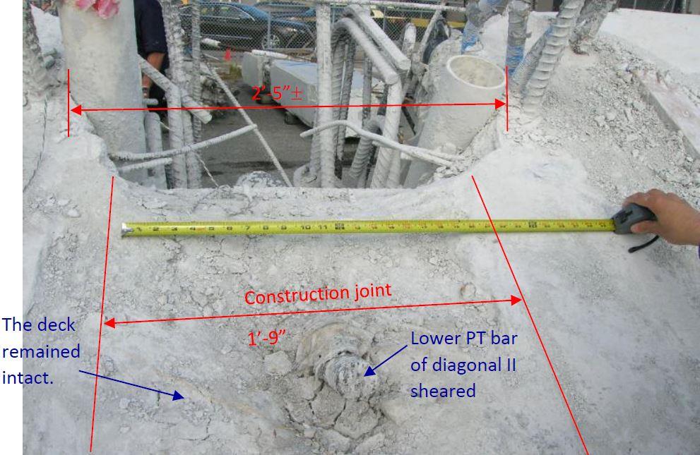
Close up plan view of deck showing the construction joint with Diagonal 11 and area of Diaphragm II that has been punched out. (Image taken from public domain OSHA report and reproduced for educational purposes under conditions of Fair Use)
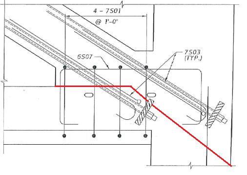
Extract of reinforcement drawing showing area of intersection between the Deck (left), Diagonal 11 (top left), Column 12 (top right) and Diaphragm II (bottom right). Red line added by Author shows the approximate line of punching shear failure. (Background image taken from public domain OSHA report and reproduced for educational purposes under conditions of Fair Use. Red failure line added by Author)
Both the NTSB extract and OSHA report detail a number of project and engineering failures that led to the collapse of the structure, a few key points are summarised below:
- Lack of understanding of the behaviour of a complex structure and whether it had redundancy.
- The design team did not understand the correct loads to use when calculating aggregate interlock and overestimated the shear capacity of the node. They also failed to specify the surface should be roughened on site, to match the calculation assumptions.
- The independent reviewer only checked the capacity of the main elements, not the capacities of the nodes or the individual construction stages.
- The independent reviewer stated that inadequate funds were provided for a full check.
- The seriousness of the cracking was not recognised by the designers, with the design engineers stating numerous times that the cracks were not a concern.
- Lack of ownership and responsibility taken by other member of the project team, including contractor, client and the independant Construction Engineer and Inspector.
- The carriageway below the structure was not closed during the re-tensioning of the Diagonal 11, this would have prevent the deaths that occurred to road users below the bridge.
One aspect of this project that stuck out immediately for me, but that was not really mentioned by either the NTSB or OSHA, but that I feel should have been highlighted was the unusual and arguably unnecessarily complicate outline design. It was decided that the structure should be made to look like a cable stayed structure, but not be a cable stayed structure, this led to the need for fake piers, fake steel tubes and the odd truss deck arrangement, with diagonals of varying angles. Secondly, if an irregular truss structure is required, why choose concrete, a material that is great in compression but needs significant reinforcement or post/pre-tensioning in tension? Adopting a more standard cable stayed steel structure would have been more conventional and would have removed a number of the challenges of this scheme. For me the adoption of a needlessly odd structural form, with ill-suited materials should also have been considered as a root-cause. I sadly suspect the only reason this structural form, that led to unnecessary risk and contributed to loss of life, was adopted purely for reasons of aesthetics.
●
●